Time to put more science on this blog, specifically related to my research. 🙂
Part of my research is about looking at crystal defects, more specifically line defects called dislocations. These phenomena are missing half planes of atoms in a crystal structure.
In an ideal world there is a certain spacial configuration of specific atoms (like carbon in diamond) that is energetically the most stable with minimal entropy (or chaos). This was assumed to be all the way up to the early 1930s until certain individuals, such as Egon Orowan started looking at crystal plasticity, the ability for a material to deform without breaking. Deformation experiments were carried out on metals and alloys to assess their strength and breaking point. Oddly, the calculations did not match the experimental results. It turned out that materials were a lot weaker, by several orders of magnitude, than was presumed. Around 1932 Orowan and Taylor simultaneously proposed the existence of missing atoms in the crystal structure to explain the observed weakness in materials. And thus was born the theory of dislocation glide to accomodate plastic deformation. Below you can see two dislocations in an otherwise perfect atomic lattice. These are the so called end-members. Normally dislocations form a mix between the two.
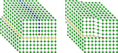 On the left is shown a line dislocation (pointing inwards below the red atom) with the blue atoms representing an extra half plane above the dislocation. The yellow atoms highlight the glide plane over which the dislocation line moves. On the right is shown a screw dislocation. Again the dislocation line points into the screen at the red atom. Think of this type of dislocation as a tear in a sheet of paper.
Not much later on, with the invention of the electron microscope, dislocations were proven to be real and have been observed in any material conveivable including upper mantle rocks which is what I am interested in.
A region in the Earth at depths between 80km and 400km there is one dominant mineral present called olivine. It is otherwise known as Peridot. This region in the Earth also experiences anything from brittle deformation at shallow depths, where Earth quakes occur, to plastic deformation.
(Don’t be fooled to think that there is a huge magma ocean deep in the Earth just because volcanoes spew out molten rocks. Volcanoes only exist in very specific settings, mostly at plate margins. The presence of subducted water at those locations greatly enhances the melting point of rocks.)
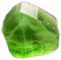 Olivine (Fe,Mg)2SiO4 otherwise known as peridot. This specimen comes from a mine in Pakistan and is about 2 cm long.
So in order to understand how the Earth works, i.e. mountain building, formation and destruction of oceanic crust, earth quakes and stress states in the Earth’s lithosphere we need to know about the strength of the rocks in the Earth. Knowing that dislocations in materials greatly reduce its strength means that they can essentially not be ignored and have to be studied.
This is where I come in. 🙂 Not only is it the above that interests me, but also the applications. For years now have geophysicists imaged the inside of the Earth by recording sound waves (seismic waves) as they are reflected and refracted in the Earth and returned to the geophones connected to a seismometer. The seismic waves can come from either Earthquakes or explosions.
The Earth is highly anisotropic in nature, therefore the understanding of a material’s behaviour to the propagation of seismic waves needs to be carried out in the lab. My study attemps to systematically prove or disprove that deformed rocks in the Earth, containing these dislocations, can slow down and attenuate (dampen) these seismic waves.
Other factors that play a role are partial melts in rocks, grain size, water and of course temperature. That makes this study not easy!! 😀
Below is shown an electron microscope image of decorated dislocations (by oxidation) in a synthetic (home made) deformed olivine aggregate.
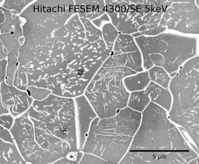 Electron microscope image of dislocations (short white lines) in several grains of synthetic (home made) deformed olivine. Using image manipulation software I can work out the dislocation density.
So there you have it. If anything is unclear, please leave a comment. I’d only be too happy to clarify. 🙂

Yes lego, exactly! I once did a science communication workshop and quickly realised that my ability to use analog examples to explain science to the average Joe is very limited indeed. However, it wont stop me from getting excited about crystal defects 😉
Crystal defects!
ok, I must admit I didn’t read the entire post, but I LOVED crystal defects @ university! I just love thinking about that perfect little, even smallar than microscopic world ( I don’t remember the word..) that world where buildingblocks fit together like lego, and crystal defects actually make sense..
sigh 🙂
speak to you soon!
C